Fixing an He-Ne Laser
I acquired some lasers, one out of the bin at Reading and another, donated by a friend at university in California (thanks!), they were broken, but thats no hinderance to fun and learning. The first two lasers were He-Ne lasers, the third was an Argon laser. Fortunately, the laser tubes were intact, and (as usual) the only problems with them were the mysterious electronics - someone let the magic smoke out!
(Very) Basic Laser Theory
Lasers operate by pumping a lasering medium to produce a large population of an excited state. Through molecular interactions, the excitation energy is transferred to an emitting species, which subsequently decay releasing light.
The process of pumping involves the input of energy, and for a He-Ne laser, the pumping is achieved by electrical discharge by a high voltage supply which creates an excited state plasma.
Laser #1: Silver-star Laser 201 (He-Ne)
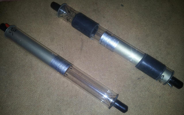
The Laser Tubes
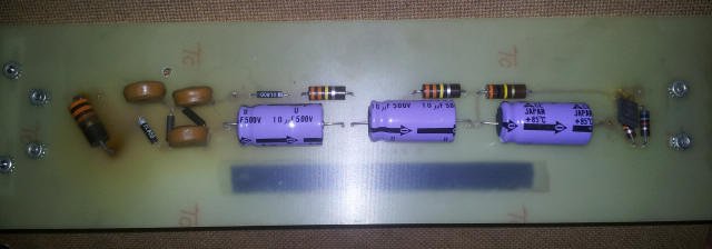
The Laser Powersupply
Turns out there was actually nothing electrically wrong with this unit: other than a loose resistor, a little re-touching and it was good to go; but still, it's a good opportunity to figure out how a laser works.
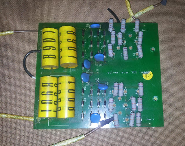
It looks like a pretty basic voltage-multiplier, in particular, we can identify several key architectural features:
This resembles a Greinacher Voltage doubler (and several other voltage multiplier topologies, see Wikipedia) - okay this one looks to be a little more complicated than the regular ones, but on mapping out the schematic perhaps we can figure it out.
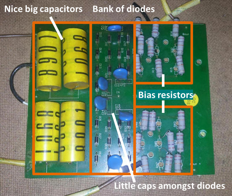
Evidently, connections B and D are the live high-tension supplies, and it goes to figure that A and C are the high-tension grounds. Notice, many of the components are identical, and in series. This is likely to increase the power handling capabilities of the components - whilst the current demand is pretty low for a laser, the voltage demand is high. Say, 1.4kV @ 50mA gives a max power of 70W. Thats really quite high for little components! Lets look at the individual components:
- Diodes = 1N4007 (1kV, 10A)
- Resistors = 27kohm, probably 1W
- Small caps = (markings: BS415, X1Y2, EW1 CS472M), 250V, 10nF
- Big caps = 8901's, 7.5uF, 450V
After combining the parallel caps, and the series diodes and resistors into single components, we arrive at a schematic far less daunting. In fact, it nearly makes sense. We can now recognise some of the basic elements of the voltage multiplier topology. There's a clear symmetry to the schematic, and with four high voltage output leads I guess we're dealing with dual output multiplier circuit, perhaps with each multiplying the opposite phase such that the output between the multipliers, is double the factor of each. Starting with the smallest units behind the current limiting resistors, we have immediately recognisable, a little voltage doubler.
Extending the analysis, we see that the doubler is incorporated as part of a larger voltage tripler unit - extending it further still, and we see that the tripler is part of a quadrupler. Hence we have two quadrupler circuits, arranged in anti-phase. This gives us an indication as to the connectivity of the four high-voltage output leads. Having already established that B and D are the high tension supply outputs, then in terms of an anti-phase multiplier, connection A would be the return for connection D, and connection C would be the return for connection B.
These voltage multipliers work on AC. They bump up the voltage by controlling the discharge of the capacitors, such that they charge on one AC half-cycle and discharge, in series with the driving voltage on the other half-cycle. Since the capacitor discharges in series with the alternate half-cycle, the two voltages add together. Since each capacitor is charged to the same drive-voltage, each one adds the drive voltage to the input voltage, hence `V_("out")=4V_("in")`
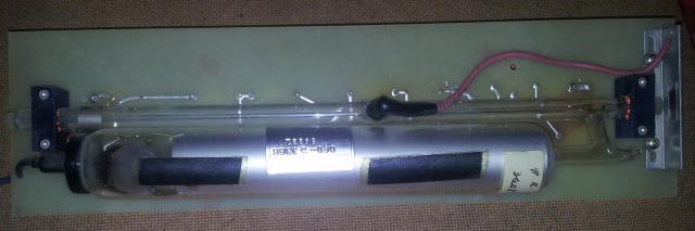
Laser #2: Spectra-Physics Model 155 Laser (He-Ne)
The second laser, pulled from a bin, was not in quite such good shape. The tube's getter (the desiccating and oxygen-scavenging additive, typically some reactive group 1 element) had gone, indicating the hermetic seal on the tube has failed, and the final stage bias resistor had blown. Unfortunately, this one was rightly scapped, but still, worth learning from.
The power supply circuitry for this device was much simpler than the first in construction, although the actual circuit was a little more complex. The NPN transistor, electrolytics and 300K-330K resistors provide some regulation to the output voltage.
- 926M J E3439 (MJE3439) NPN High-voltage power transistor, 300mA, 450V
- Electrolytics = 10uF 500V
- Ceramics = Motorola 500M Z5U, 6kV, 500pF
- Diodes = DL800, 25mA, 8kV