Using the AD9850/AD9851 DDS with an Arduino MEGA
DDS (Direct Digital Synthesis) is a means of generating AC signal waveforms programmatically. Two very common and cheap DDS modules available are available on ebay, the AD9850 and AD9851, but being digital devices, require a microprocessor to initialise and control them. The AD9850 pictured below, costs around £7GBP. These DDS units can be interfaced either via parallel or serial connections, but I don't really see an advantage to using the parallel bit mode, it requires too many wires, so here we'll only concentrate on the serial interface.
In addition to GND and 5V, the DDS requires four control lines:
- Data (serial)
- Clock
- Load
- Reset
These are used to send the control bits from the microcontroller to the DDS unit.
 |
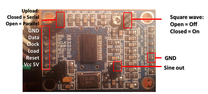 |
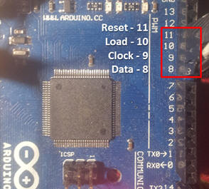
| Figure 1: Arduino Mega | Figure 2: A cheapo AD9850 DDS |
All six required connections can be wired directly to the Arduino.
Whilst its quite possibly to implement a syncronous serial instruction, the easiest way is to use a form of 'bit-banging' - on each clock tick, we simply change the logic level of the data line. The basic procedure for controlling the DDS is:
- Set all connections to logic low (initialise)
- Signal RESET high and clock
- Signal LOAD high and clock
- Send the initialisation bits down the DATA line
Below is some pretty basic code that can be utilised to control the Arduino. The software is not interactive, and so requires recompilation to change the frequency.
//AD9850 DDS test

#define DDS_CLOCK 125000000

#define DATA 8
#define CLOCK 9 //pin connections for DDS
#define LOAD 10
#define RESET 11

void setup()
{
pinMode (DATA, OUTPUT);
pinMode (CLOCK, OUTPUT);
pinMode (LOAD, OUTPUT);
pinMode (RESET, OUTPUT);
AD9850_init();
AD9850_reset();
SetFrequency(100);

}

void loop(){}

void SetFrequency(unsigned long frequency)
{
unsigned long tuning_word = 180+(frequency * pow(2, 32)) / DDS_CLOCK;
// unsigned long tuning_word = (frequency * 4294967296) / DDS_CLOCK;
digitalWrite (LOAD, LOW);

shiftOut(DATA, CLOCK, LSBFIRST, tuning_word);
shiftOut(DATA, CLOCK, LSBFIRST, tuning_word >> 8);
shiftOut(DATA, CLOCK, LSBFIRST, tuning_word >> 16);
shiftOut(DATA, CLOCK, LSBFIRST, tuning_word >> 24);
shiftOut(DATA, CLOCK, LSBFIRST, 0x0);
digitalWrite (LOAD, HIGH);
}

void AD9850_init()
{

digitalWrite(RESET, LOW);
digitalWrite(CLOCK, LOW);
digitalWrite(LOAD, LOW);
digitalWrite(DATA, LOW);
}

void AD9850_reset()
{
//reset sequence is:
// CLOCK & LOAD = LOW
// Pulse RESET high for a few uS (use 5 uS here)
// Pulse CLOCK high for a few uS (use 5 uS here)
// Set DATA to ZERO and pulse LOAD for a few uS (use 5 uS here)

// data sheet diagrams show only RESET and CLOCK being used to reset the device, but I see no output unless I also
// toggle the LOAD line here.

digitalWrite(CLOCK, LOW);
digitalWrite(LOAD, LOW);

digitalWrite(RESET, LOW);
delayMicroseconds(5);
digitalWrite(RESET, HIGH); //pulse RESET
delayMicroseconds(5);
digitalWrite(RESET, LOW);
delayMicroseconds(5);

digitalWrite(CLOCK, LOW);
delayMicroseconds(5);
digitalWrite(CLOCK, HIGH); //pulse CLOCK
delayMicroseconds(5);
digitalWrite(CLOCK, LOW);
delayMicroseconds(5);
digitalWrite(DATA, LOW); //make sure DATA pin is LOW

digitalWrite(LOAD, LOW);
delayMicroseconds(5);
digitalWrite(LOAD, HIGH); //pulse LOAD
delayMicroseconds(5);
digitalWrite(LOAD, LOW);
// Chip is RESET now
}
A slightly more complicated Arduino program below allows an Arduino with an Ethernet Shield to control the DDS through a web-based interface.
/*
Based on the Arduino_with_Ethernet_Shield by Rui Santos Visit: http://randomnerdtutorials.com for more arduino projects
Updated by PHIL
*/

#include <SPI.h>
#include <Ethernet.h>

//AD9850 DDS test

#define DDS_CLOCK 125000000

#define DATA 8
#define CLOCK 9 //pin connections for DDS
#define LOAD 10
#define RESET 11

//Ethernet setup
int led = 4;
int pos = 0;
byte mac[] = { 0xDE, 0xAD, 0xBE, 0xEF, 0xFE, 0xED }; //physical mac address
byte ip[] = { 192, 168, 0, 177 }; // ip in lan (that's what you need to use in your browser. ("192.168.1.178")
byte gateway[] = { 223, 223, 223, 0 }; // internet access via router
byte subnet[] = { 255, 255, 255, 0 }; //subnet mask
EthernetServer server(80); //server port
String readString;

void setup() {
//setup Ethernet
// Open serial communications and wait for port to open:
Serial.begin(9600);
while (!Serial) {
; // wait for serial port to connect. Needed for Leonardo only
}
pinMode(led, OUTPUT);
// start the Ethernet connection and the server:
Ethernet.begin(mac, ip, gateway, subnet);
server.begin();
Serial.print("server is at ");
Serial.println(Ethernet.localIP());

//Setup DDS
pinMode (DATA, OUTPUT);
pinMode (CLOCK, OUTPUT);
pinMode (LOAD, OUTPUT);
pinMode (RESET, OUTPUT);
AD9850_init();
AD9850_reset();
SetFrequency(10000);

}


void loop() {
// Create a client connection
EthernetClient client = server.available();
if (client) {
while (client.connected()) {
if (client.available()) {
char c = client.read();

//read char by char HTTP request
if (readString.length() < 100) {
//store characters to string
readString += c;
//Serial.print(c);
}

//if HTTP request has ended
if (c == '\n') {
Serial.println(readString); //print to serial monitor for debuging

client.println("HTTP/1.1 200 OK"); //send new page
client.println("Content-Type: text/html");
client.println();
client.println("<HTML>");
client.println("<HEAD>");
client.println("<TITLE>Web-based Interface</TITLE>");
client.println("</HEAD>");
client.println("<BODY>");
client.println("<H1>Web-based Interface</H1>");
client.println("<hr />");
client.println("<br />");
client.println("<H2>Arduino AD9850 Control</H2>");
client.println("<br />");
client.println("<a href=\"/?AD9850_reset\"\">AD9850_reset</a><br />");
client.println("<a href=\"/?set100\"\">100Hz</a><br />");
client.println("<a href=\"/?set10k\"\">10kHz</a><br />");
client.println("<a href=\"/?set22M\"\">22MHz</a><br />");
client.println("<form method=get action=.><input type=text name=freq /><input type=submit /></form>");
client.println("<br />");
client.println("<hr />");
client.println(readString);
client.println("<hr />");
client.println("</BODY>");
client.println("</HTML>");

delay(1);
//stopping client
client.stop();
//controls the Arduino if you press the buttons
if (readString.indexOf("?button1on") >0){
digitalWrite(led, HIGH);
}
if (readString.indexOf("?set100") >0){
AD9850_init();
AD9850_reset();
SetFrequency(100);
}
if (readString.indexOf("?set10k") >0){
AD9850_init();
AD9850_reset();
SetFrequency(10000);
}
if (readString.indexOf("?set22M") >0){
AD9850_init();
AD9850_reset();
SetFrequency(22000000);
}
if (readString.indexOf("?AD9850_init") >0){
AD9850_init();
}
if (readString.indexOf("?AD9850_reset") >0){
AD9850_reset();
}

//clearing string for next read
readString="";

}
}
}
}
}

void SetFrequency(unsigned long frequency)
{
unsigned long tuning_word = 180+(frequency * pow(2, 32)) / DDS_CLOCK;
// unsigned long tuning_word = (frequency * 4294967296) / DDS_CLOCK;
digitalWrite (LOAD, LOW);

shiftOut(DATA, CLOCK, LSBFIRST, tuning_word);
shiftOut(DATA, CLOCK, LSBFIRST, tuning_word >> 8);
shiftOut(DATA, CLOCK, LSBFIRST, tuning_word >> 16);
shiftOut(DATA, CLOCK, LSBFIRST, tuning_word >> 24);
shiftOut(DATA, CLOCK, LSBFIRST, 0x0);
digitalWrite (LOAD, HIGH);
}

void AD9850_init()
{

digitalWrite(RESET, LOW);
digitalWrite(CLOCK, LOW);
digitalWrite(LOAD, LOW);
digitalWrite(DATA, LOW);
}

void AD9850_reset()
{
//reset sequence is:
// CLOCK & LOAD = LOW
// Pulse RESET high for a few uS (use 5 uS here)
// Pulse CLOCK high for a few uS (use 5 uS here)
// Set DATA to ZERO and pulse LOAD for a few uS (use 5 uS here)

// data sheet diagrams show only RESET and CLOCK being used to reset the device, but I see no output unless I also
// toggle the LOAD line here.

digitalWrite(CLOCK, LOW);
digitalWrite(LOAD, LOW);

digitalWrite(RESET, LOW);
delayMicroseconds(5);
digitalWrite(RESET, HIGH); //pulse RESET
delayMicroseconds(5);
digitalWrite(RESET, LOW);
delayMicroseconds(5);

digitalWrite(CLOCK, LOW);
delayMicroseconds(5);
digitalWrite(CLOCK, HIGH); //pulse CLOCK
delayMicroseconds(5);
digitalWrite(CLOCK, LOW);
delayMicroseconds(5);
digitalWrite(DATA, LOW); //make sure DATA pin is LOW

digitalWrite(LOAD, LOW);
delayMicroseconds(5);
digitalWrite(LOAD, HIGH); //pulse LOAD
delayMicroseconds(5);
digitalWrite(LOAD, LOW);
// Chip is RESET now
}