Superheterodyne NMR Spectrometer
Block Diagram
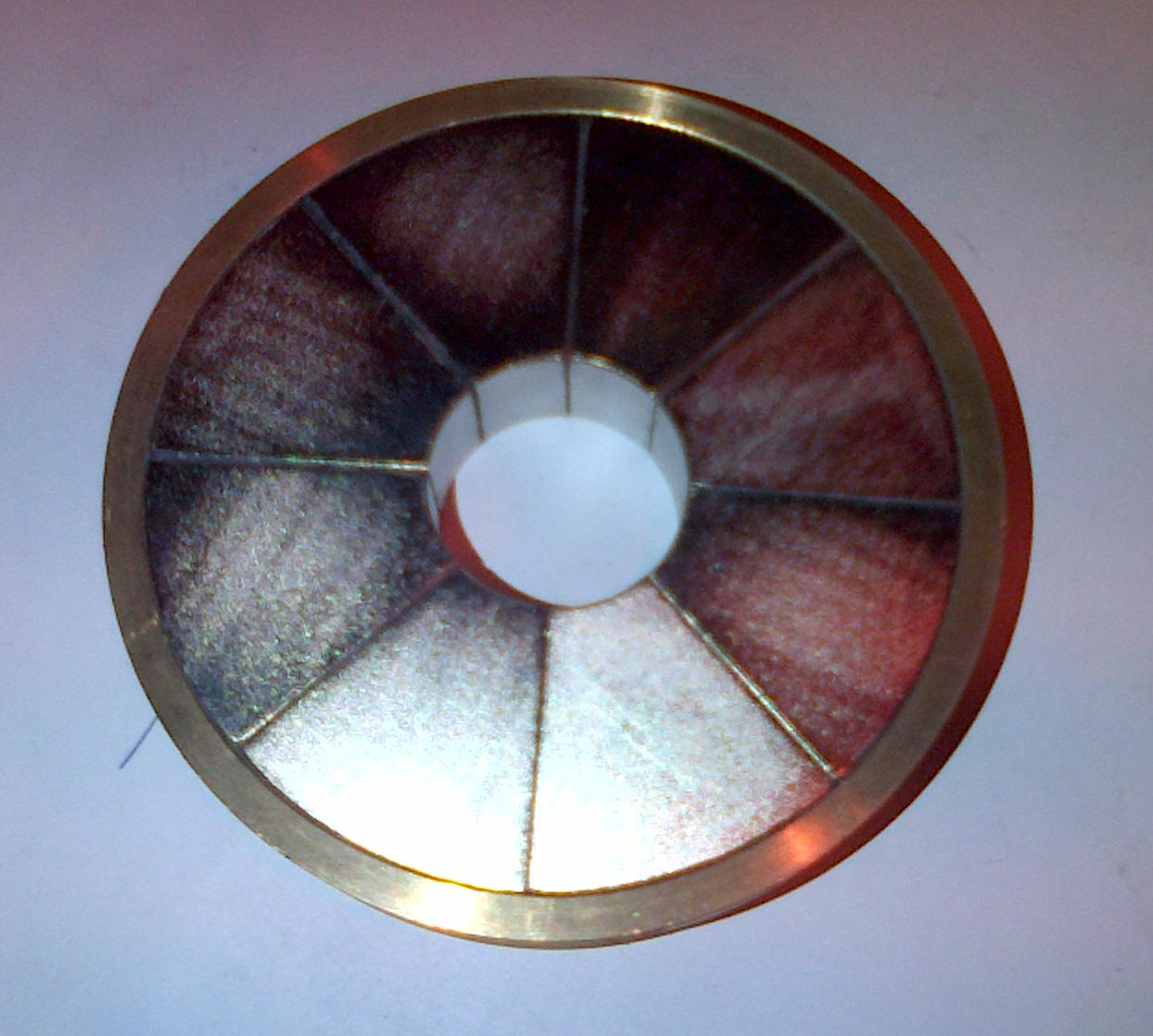
With a strength of 1.08T, the magnet results in a proton resonance frequency of 44.2MHz, according to the proton gyromagnetic equation. Our magnet is of Neodymium construction arranged as a Halbach n=2 array. This arrangement minimises the stray magnet field lines outside the magnet, maximises the magnet field strength in the cavity, and aligns the field strength lines as to afford an optimal field homogeneity.
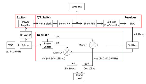
We de-tune the VCO to somewhere close to 44.2MHz, around 10kHz above, or below, the required frequency. This is chosen for convenience – optimally, the VCO would be tuned to exactly the resonant frequency, but by choosing a frequency 10kHz different, once the NMR echo is amplified it needs to be mixed down to audio frequencies (0-44.1kHz), ie., 44.2MHz-44.19MHz=10kHz. Since the mixer combines the LO (local oscillator) and RF (nmr) signals to produce the sum and difference of frequencies, using the already detuned VCO, this eliminates the need for a separate local oscillator for the mixer.
By applying a narrow top-hat function to the VCO using opening the RF switch, the TR switch and also turning off the RFPA (power amplifier) simultaneously, once the RF wave packet hits the sample it will spread to an envelope of frequencies simultaneously exciting all the different magnetic environment.
The system will still work using only one mixer, and with the loss of the phase shifter, however their incorporation is useful. The Fourier transform of the audio input performed on the PC requires two inputs, sine and cosine – whilst these are exactly the same signal, one of the channels shifted in phase by 90degrees.
44.2MHz has a time period of approximately 25ns, and so a 90deg phase shift corresponds to a delay of one signal by 6.5ns. As discussed, a single datapoint could literally correspond to any signal frequency or phase, but having access to its derivative simultaneously allows the algorithm to determine immediately the phase and the frequency. Software can perform this for us, but since the audio has two input channels it makes sense to do this in hardware which means the FT algorithm can operate in real-time and without any additional processing.
The IQ Mixer is slightly simplified: the device has four inputs and two outputs – the ins and outs both have two leads, one is usually connected to the ground. The output pair is more important, as neither of the leads are connected to the ground. These two outputs are the +ve and –ve terminals, and one is always the opposite voltage to the other. This can be very useful because if any noise gets into the circuit it can be easily removed using an op-amp configured for Common Mode Rejection (CMRR).
In the below schematic, the phase-shifter has been properly called LO quadrature generation. Quadrature refers to the two signals being 90degrees apart. The far right blocks ‘3rd order Sallen-Key LPF’ refer to a particular type of ‘active’ (or op-amp based) low pass filters.
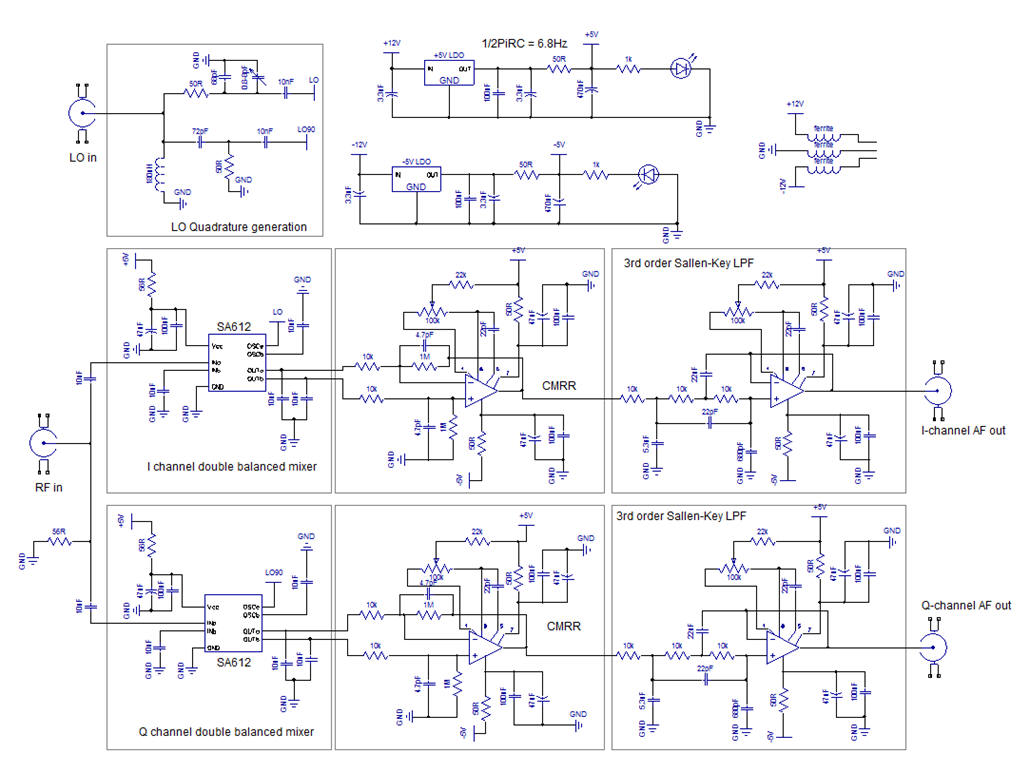
Notice that the ‘double balanced mixers’ have two wires going to the CMRR block. The CMRR op-amps remove any common mode noise, and output only a single ‘live’ signal wire which then passes through the LPF. The Outputs ‘I/Q-channel AF out’ (AF=audio frequency) are wired to the soundcard.
The form of the NMR echo signal is one of the familiar FID ‘free induction decay.’ This contains all the resonant frequencies of the nuclei combined, but down-mixed from 44.2MHz +/- 10ppm (±44Hz) to 10kHz +/-44Hz.