Impedance Matching
Using the example of matching the 200R DDS at 22.1MHz to a 50R amplifier, there are several approaches we could employ.
Parallel Resistor
The first approach is to use a parallel resistor to achieve a combined resistance equal to the load, where the source resistance is larger than the load. To do this we use the parallel resistance equation,
`Z_L=1/(1/R_l+1/R_s)=(R_lR_s)/(R_l+R_s)`
Hence we set the desired impedance equal the load impedance and solve for Rl.
`(1/Z_L-1/R_s)^(-1)=R_l`
Thus for the example in question we can calculate the required value,,
`(1/(50Omega)-1/(200Omega))^(-1)=R_l=66.7Omega`
Whilst an easy approach, a large power loss occurs across the introduced resistor and so the approach is not often desirable.
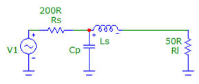
L-pad matching: Capacitor and Inductor
Rather than using a resistor we can instead use a capacitor and an inductor. Using a parallel capacitance we can match the real component of the impedance, but with this is introduced an imaginary reactance. To complete the match, we must then cancel the imaginary component which can be achieved using a series inductance. Recall that the sign of the impedance of a capacitor is negative whereas that of an inductor is positive.
Matching Using a Transformer - a Wide-band solution
Impedance matching is important to ensure that the maximum power is transferred from the source to the load. Whilst there are various ways of achieving this, the use of a transformer enables a match over a wideband of frequencies, which contrasts to impedance matching networks which are optimal only over a tight frequency band. In the case of matching the AD9851 DDS (with a source impedance of 200R) to the frequency doubler (with a load impedance of 50R), we make use of a 2:1 RF transformer.

For the sake of simplicity, say the source provides 1W of power, we want this full power to be delivered to the load. Using Ohms Law and the Power Law, we can express the voltage provided by the 200R source,
`P=IV=V^2/R` and `PR=V^2`, then `sqrt(1W*200Omega)=V=14.14V`
Then the load with an impedance of 50R, for a power of 1W delivered we can calculate the required drive voltage,
`sqrt(1W*50Omega)=V=7.07V`
These calculations indicate that for the same power to be delivered, the voltage on the 50R load must be half that provided by the 200R source. To achieve this, we use the voltage/current transformer equation,
`V_"primary"/V_"secondary"=n_"primary"/n_"secondary"=I_"secondary"/I_"primary"`
With a voltage ratio of 2:1, we must drop the voltage by half, and this requires
`V_"primary"/V_"secondary"=n_"primary"/n_"secondary"=(14.14V)/(7.07V)=2/1`
Hence the primary side of the transformer, which faces the 200R source, should have the twice the windings of the secondary.
Component Selection
Coilcraft manufacture a wide array of RF transformers, and in order to provide a bias voltage to the frequency doubler we require a transformer centre tapped on the secondary. For the sake of utility, we opted for the PWB-2-CLB, which is centre tapped on both windings. This component has a bandwidth of 0.13-285MHz, can handle a current of 250mA, exhibits an insertion loss of 0.30dB and presents the DC resistance of 105mR on the primary and 130mR on the secondary.